

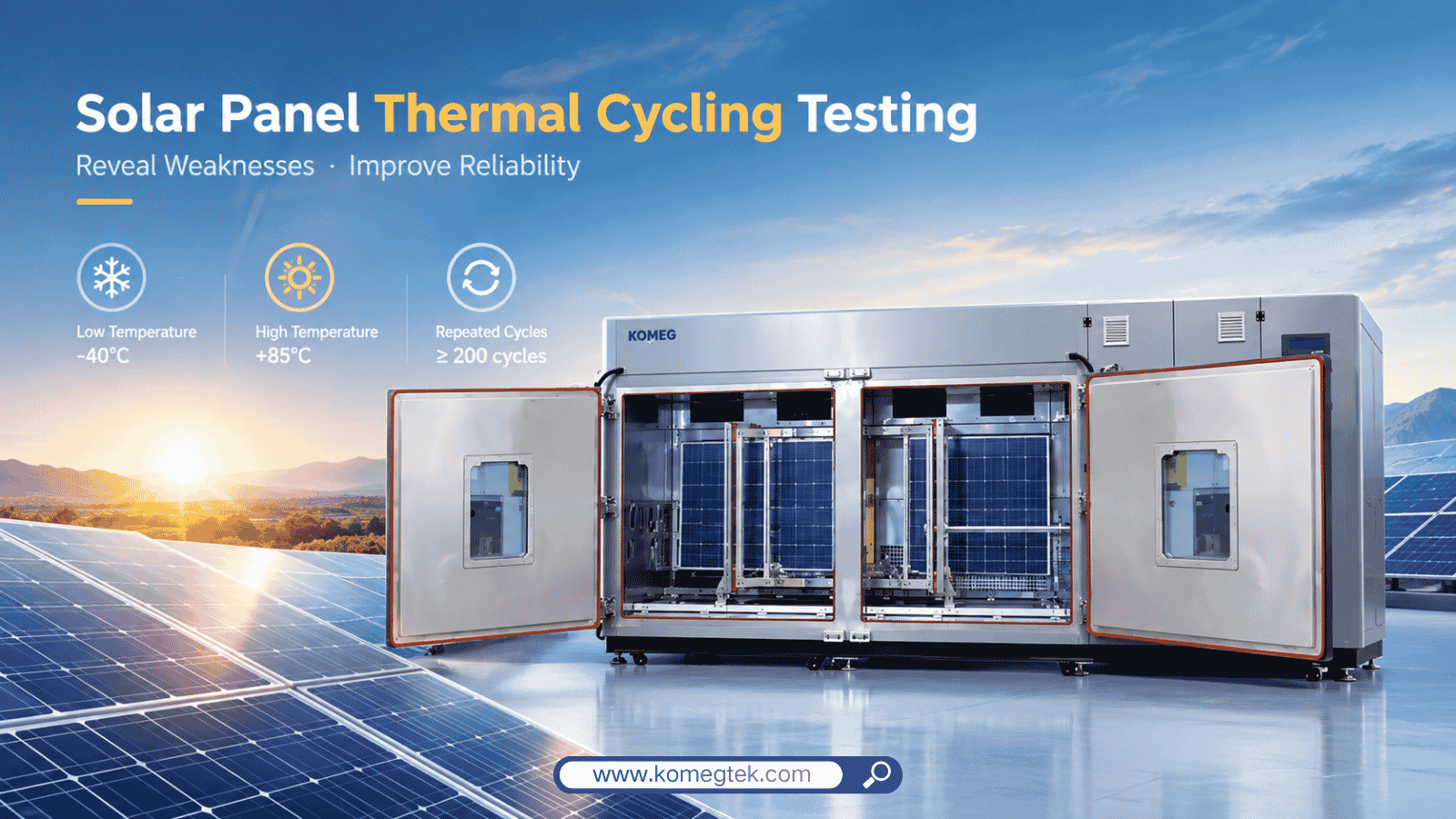
Solar panels are designed to operate outdoors for many years, where temperatures can change dramatically between daytime and nighttime, summer and winter, and different weather conditions. But repeated temperature changes do more than simply make a PV module hotter or colder. They create mechanical stress inside the module, particularly where different materials expand and contract at different rates.
This is why thermal cycling testing is an important part of solar panel environmental testing and PV module reliability testing.
During a thermal cycling test, a solar panel is repeatedly exposed to high and low temperatures inside an environmental test chamber. The purpose is not simply to determine whether the panel can operate at a particular temperature. The more important question is whether repeated thermal stress can cause hidden damage that eventually affects electrical performance, mechanical integrity, or long-term reliability.
What Is Thermal Cycling Testing for Solar Panels?
Thermal cycling testing exposes a PV module to repeated changes between defined high and low temperatures. Instead of maintaining the module at one temperature, the environmental test chamber repeatedly heats and cools the test sample according to a controlled temperature profile.
This creates a repeated expansion-and-contraction cycle throughout the module.
A typical PV module contains multiple materials, including silicon solar cells, glass, encapsulants, metallic interconnections, soldered connections, backsheets or rear glass, frames, junction boxes, and sealants. These materials do not all respond to temperature changes in exactly the same way.
As temperature increases, materials expand. As temperature decreases, they contract. Because the materials are bonded together, their movement is constrained. Repeating this process can generate thermomechanical stress at interfaces and connections.
The important point is that thermal cycling is therefore not simply a temperature test. It is also a mechanical fatigue test caused by repeated temperature changes.
IEC 61215-2:2021 establishes test procedures for terrestrial PV module design qualification and type approval and applies to technologies including crystalline silicon and thin-film flat-plate modules. The standard’s overall objective is to assess electrical characteristics and demonstrate the ability of the module to withstand prolonged outdoor exposure within reasonable test constraints.
Why Does Temperature Cycling Create Stress Inside a PV Module?
The main reason is the difference in thermal expansion between materials.
Every material has a coefficient of thermal expansion, commonly referred to as CTE. When two materials with different CTE values are bonded together, they tend to expand and contract by different amounts when their temperature changes.
A PV module is essentially a multilayer structure. The glass, silicon cells, encapsulant, metallic ribbons, solder joints, backsheet, frame, and other components are mechanically connected.
During heating:
Temperature increases → materials expand → expansion is constrained → mechanical stress develops
During cooling:
Temperature decreases → materials contract → contraction is constrained → mechanical stress develops
When this happens repeatedly, the stress can accumulate in vulnerable areas.
The effect can be particularly important around solder joints, cell interconnections, ribbons, busbars, junction boxes, and other locations where different materials are connected.
This is why a solar panel may appear visually normal after a limited number of cycles while still developing degradation at internal electrical or mechanical connections.
What Can Happen to Solar Panels During Thermal Cycling?
Thermal cycling does not necessarily cause one single type of failure. The actual degradation mechanism depends on the module design, materials, manufacturing process, temperature profile, number of cycles, and other environmental stresses.
Several failure mechanisms are particularly important.
1. Solder Joint Fatigue
Soldered electrical connections are exposed to repeated mechanical movement caused by thermal expansion and contraction.
Each temperature cycle produces a small amount of deformation. Over many cycles, this repeated deformation can contribute to fatigue in solder joints and electrical interconnections.
The problem is that solder fatigue does not always produce an immediately visible failure. A connection may gradually develop higher electrical resistance before eventually becoming significantly degraded.
NREL research has identified loss of electrical connections as a PV module reliability concern associated with thermal cycling and mechanical movement, including broken solder bonds and increased series resistance.
2. Solar Cell Microcracks
Silicon solar cells are relatively thin and mechanically sensitive structures. Repeated thermomechanical stress can contribute to the initiation or growth of cracks.
Some cracks may be difficult to detect through a conventional visual inspection.
A module can therefore leave a thermal cycling test with no obvious external damage while internal cell damage has already developed.
Electroluminescence (EL) imaging is often useful for identifying these types of changes because it can reveal electrically inactive regions and cell-level defects that are not necessarily visible from the module surface.
NREL accelerated testing has reported cell crack growth in crystalline silicon modules subjected to repeated thermal cycling.
3. Increased Electrical Resistance
When interconnections or soldered joints become mechanically damaged, electrical resistance can increase.
This can affect current flow through the module and contribute to power loss.
In other words, the environmental stress does not need to completely break an electrical connection to become a reliability problem. Partial degradation may already affect electrical performance.
For this reason, thermal cycling evaluation should be considered together with appropriate electrical measurements before, during, or after the environmental test sequence.
4. Delamination
A PV module contains multiple bonded layers. Repeated thermal expansion and contraction can place stress on interfaces between these materials.
If adhesion is insufficient or the material combination is vulnerable, delamination may develop.
Delamination can become more serious when combined with moisture exposure because separated interfaces may provide pathways for moisture ingress.
NREL has identified delamination and subsequent moisture ingress as important PV module degradation mechanisms, with damp heat and humidity-freeze testing used to investigate related vulnerabilities.
5. Degradation Around Electrical Connections
The junction box, ribbons, busbars, cell connections, and other electrical interfaces are also exposed to thermal movement.
A thermal cycle therefore affects more than the silicon cells themselves.
In a well-designed environmental reliability program, engineers need to consider the complete module structure rather than focusing only on the photovoltaic cells.
This is one reason why PV module environmental testing is fundamentally different from testing an individual solar cell.
What Temperature Range Is Used for Solar Panel Thermal Cycling?
One commonly referenced PV module thermal cycling range is approximately -40°C to +85°C.
The low-temperature stage represents severe cold conditions, while the high-temperature stage represents elevated operating or environmental temperatures.
The module is repeatedly transitioned between the two conditions according to the applicable test procedure.
The widely used IEC 61215 qualification framework has traditionally included 200 thermal cycles, while extended testing programs may use substantially more cycles. For example, IEC 62892 defines an extended thermal cycling procedure intended to differentiate modules with improved durability to thermal cycling and evaluate modules intended for locations particularly susceptible to thermal-cycling stress.
It is important not to treat one temperature range or cycle count as a universal requirement for every PV product. The applicable test conditions depend on the relevant standard, module technology, qualification program, deployment environment, and customer specification.
Recent industry testing also demonstrates why extended thermal cycling can reveal differences between module designs. In one reported test program, modules were cycled between -40°C and +85°C, with one weaker-performing module showing a 2.2% maximum-power loss and more pronounced degradation after 400 cycles.
Why Is the Temperature Ramp Rate Important?
The high and low temperature limits are only part of the test profile.
The rate at which the module changes temperature also matters.
A rapid temperature transition can create a larger temperature difference between different parts of the module. The outer surface, glass, cells, encapsulant, and internal components may not immediately reach the same temperature.
This creates thermal gradients.
For example, the chamber air may reach the programmed temperature relatively quickly while the center of a large PV module changes temperature more slowly because of its thermal mass.
This creates an important distinction between:
Chamber air temperature
and
Actual product temperature
For reliable testing, the environmental test chamber must therefore be capable of controlling the specified temperature profile while providing appropriate airflow, temperature uniformity, and heat transfer around the test sample.
Simply reaching -40°C or +85°C is not enough if the module itself does not experience the intended thermal conditions.
What Does Thermal Cycling Testing Reveal?
Thermal cycling is particularly useful for identifying weaknesses that may not appear during a short-term steady-state temperature test.
A module may operate normally at +85°C.
It may also operate normally at -40°C.
But repeated transitions between these conditions can expose problems that neither steady-state test reveals.
This is because the failure mechanism is related to repetition.
The test essentially asks:
Can the module maintain its structural and electrical integrity after repeated thermal expansion and contraction?
That makes thermal cycling particularly relevant to long-term reliability.
Research from NREL has shown that crystalline silicon modules subjected to repeated thermal cycling can exhibit gradual degradation and, in some cases, crack growth. Other accelerated testing work has investigated thermal cycling as a way to study thermomechanical fatigue in module interconnections.
Does Passing Thermal Cycling Mean a Solar Panel Will Last 25 Years?
Not necessarily.
This is an important distinction in PV reliability testing.
An environmental qualification test is not the same thing as a direct 25-year lifetime prediction.
Outdoor PV modules experience many stresses simultaneously, including:
Temperature cycling
High temperature
Low temperature
Humidity
Moisture ingress
UV exposure
Mechanical loading
Wind
Freeze-thaw conditions
Electrical bias
Corrosive environments
Thermal cycling isolates one important stress mechanism so that engineers can evaluate how the module responds to repeated temperature changes.
Other tests are required to investigate other degradation mechanisms.
This is also why accelerated lifetime testing may combine multiple stress conditions. NREL research, for example, has used thermal cycling alongside damp heat and combined stress sequences to investigate different PV module degradation mechanisms.
The correct interpretation is therefore not:
“The module passed thermal cycling, so it will definitely last 25 years.”
A more appropriate interpretation is:
“The module demonstrated resistance to the specified thermal cycling stress under the applicable test conditions.”
That distinction is important when evaluating PV module reliability.
How Is Solar Panel Thermal Cycling Tested?
A typical thermal cycling evaluation involves several stages.
Step 1: Initial Inspection and Characterization
Before environmental exposure, the module is inspected and characterized.
Depending on the test program, engineers may record electrical performance, visual condition, insulation characteristics, electroluminescence images, or other baseline data.
The purpose is to establish a reference condition.
Step 2: Install the Module in the Environmental Test Chamber
The PV module is positioned inside a temperature-controlled environmental test chamber.
For large modules, the fixture must provide appropriate support without introducing unintended mechanical constraints that could distort the test.
The chamber also needs sufficient working space and airflow around the test sample.
Step 3: Run the Thermal Cycling Profile
The chamber repeatedly moves between the specified low and high temperatures.
Temperature, transition rates, dwell conditions, and cycle count are controlled according to the applicable test procedure.
The goal is repeatable thermal stress rather than uncontrolled temperature fluctuation.
Step 4: Monitor the Test
During testing, engineers may monitor chamber temperature, sample temperature, electrical parameters, or other application-specific signals.
For large PV modules, temperature measurement at multiple locations can be particularly useful because the module may experience thermal gradients during rapid transitions.
Step 5: Post-Test Inspection
After the specified number of cycles, the module is evaluated again.
Depending on the qualification program, engineers may compare:
Maximum power
Current and voltage characteristics
Insulation performance
Visual condition
EL images
Interconnection condition
Delamination
Cracking
Other mechanical or electrical characteristics
The purpose is to determine whether the thermal stress produced measurable degradation or evidence of failure.
What Should You Look for in a Solar Panel Thermal Cycling Test Chamber?
The chamber is a critical part of the test system.
For small laboratory samples, a conventional solar panel test chamber may be sufficient. However, full-size PV modules present a different challenge because of their dimensions and thermal mass.
Important factors include:
Chamber Size
The chamber must provide enough working space for the module and its fixtures while maintaining appropriate airflow.
KOMEG offers standard temperature and environmental chambers in different volumes, while larger PV module applications can be configured with customized chamber dimensions. KOMEG’s solar panel test chamber solutions are specifically positioned for PV module thermal cycling, humidity-freeze, and 85°C/85% RH testing.
Temperature Range
The chamber must cover the required high and low temperatures of the applicable test profile.
KOMEG temperature test chambers are available in configurations extending from low temperatures to elevated temperatures, with standard models from 64 L to 1000 L and customized solutions for more specialized applications.
Temperature Uniformity
A large solar panel should not experience excessive temperature differences simply because of its position inside the chamber.
Uniform airflow and appropriate chamber design are therefore important for repeatable testing.
Temperature Transition Capability
The chamber needs to reproduce the required thermal profile consistently.
For applications involving frequent or accelerated cycling, the heating and cooling capability becomes especially important.
KOMEG also provides dedicated temperature cycling chambers with configurations designed for repeated temperature changes and different ramp-rate requirements.
Fixture and Cable Access
Solar panel testing may require electrical connections to remain accessible during the test.
Cable ports, mounting fixtures, sample supports, and internal clearance should therefore be considered during chamber design.
Large-Format and Multiple-Module Testing
When several PV modules need to be tested simultaneously, or when the module dimensions exceed the working space of a standard chamber, a walk-in environmental chamber may be more appropriate.
KOMEG walk-in environmental chambers are available in configurations from approximately 4 m³ to 55 m³ and are designed for large products including solar panels. The chamber can be customized according to sample dimensions and the number and arrangement of products being tested.
How KOMEG Supports Solar Panel Environmental Testing
Solar panel testing is not always a simple matter of placing a module inside a standard environmental chamber.
The chamber needs to be designed around the actual test.
For individual or smaller PV module testing, a temperature or temperature-and-humidity chamber may provide the required test space and environmental control. KOMEG’s temperature and humidity chambers are available in standard sizes from 64 L to 1000 L and can be customized for specialized requirements.
For larger modules or multiple samples, a customized walk-in environmental test chamber can provide greater flexibility. Chamber dimensions, sample arrangement, thermal load, airflow, cable access, fixtures, temperature profile, and other test requirements can be considered during the design process.
This becomes particularly important when the test program goes beyond standard qualification and requires larger sample quantities, unusual fixtures, electrical monitoring, or specific temperature transition profiles.
KOMEG also has a dedicated solar panel test chamber solution designed around PV module testing, including thermal cycling, humidity-freeze, and 85°C/85% RH testing.
Thermal Cycling Is About More Than Temperature
The most important thing to understand about solar panel thermal cycling testing is that the test is not simply asking whether a PV module can survive high and low temperatures.
It is asking how the complete module responds when different materials are repeatedly forced to expand and contract together.
That repeated movement can place stress on solder joints, cell interconnections, silicon cells, encapsulation interfaces, and other components. Over time, these mechanisms may contribute to electrical degradation, cracking, delamination, or connection failure.
This is why thermal cycling remains an important part of PV module reliability testing.
For manufacturers and testing laboratories, the challenge is to reproduce the required environmental stress accurately and consistently while measuring changes in module performance.
A properly designed environmental test chamber is therefore not just a temperature-controlled box. It is part of the reliability test system.
As PV modules continue to evolve toward larger formats, new cell technologies, different encapsulation materials, and more complex module structures, understanding how those materials respond to repeated thermal stress will remain essential to long-term solar module reliability.