

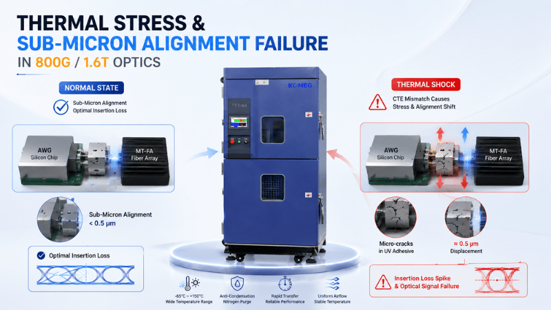
As optical communication networks move from 400G to 800G and toward 1.6T architectures, the reliability requirements of optical transceivers are becoming increasingly demanding. Higher bandwidth, greater packaging density, and tighter optical alignment tolerances leave less margin for thermal and mechanical variation.
Components such as Arrayed Waveguide Gratings (AWG), Micro-Termination Fiber Arrays (MT-FA), silicon photonics devices, optical fibers, adhesives, and precision metal packages must maintain stable optical performance throughout repeated environmental exposure.
Thermal shock testing provides an effective way to evaluate how these optical assemblies respond to rapid temperature transitions and to identify potential reliability risks before products enter large-scale deployment.
For manufacturers developing high-speed optical modules, thermal shock testing is not simply a temperature test. It is a way to evaluate whether the optical alignment, material interfaces, adhesive structures, and mechanical packaging can withstand repeated thermal stress without unacceptable changes in optical performance.
Why Thermal Shock Testing Matters for 800G and 1.6T Optical Components
The internal structure of high-speed optical assemblies combines materials with significantly different thermal expansion characteristics.
Silica optical fibers, silicon photonic chips, ceramic substrates, metal housings, polymer materials, and optical adhesives do not expand or contract at the same rate when temperature changes.
During rapid heating and cooling, this difference creates mechanical stress throughout the optical assembly.
For conventional electronic products, small dimensional changes may have limited impact. For high-density optical packaging, however, even a very small displacement can affect optical coupling and alignment.
This is particularly important for 800G and 1.6T optical devices, where multiple optical channels must remain precisely aligned to maintain stable transmission performance.
Common Thermal Failure Mechanisms in AWG and MT-FA Assemblies
Optical Alignment Drift
AWG and MT-FA assemblies depend on precise positioning between optical fibers and optical components.
Repeated thermal expansion and contraction can gradually change the relative position of the fiber array, ferrule, optical chip, or coupling structure.
Even small alignment changes can increase insertion loss or introduce channel-to-channel performance variation.
For multi-channel optical assemblies, maintaining alignment stability throughout the complete temperature profile is therefore critical.
Adhesive Micro-Cracking and Delamination
Optical assemblies frequently rely on adhesives to secure fibers, optical components, and mechanical structures.
Rapid temperature transitions can generate repeated stress at material interfaces. When the thermal expansion characteristics of the bonded materials differ significantly, the adhesive layer may experience tensile, compressive, or shear stress.
Over repeated cycles, this can contribute to micro-cracking, delamination, loss of mechanical strength, or moisture penetration.
These failures may not be immediately visible, making environmental testing particularly important during product qualification.
Fiber and Ferrule Stress
MT-FA structures require precise fiber positioning and stable mechanical support.
Rapid temperature changes can create stress between the optical fiber, ferrule, adhesive, and surrounding housing.
If the mechanical design does not adequately accommodate thermal expansion, the resulting stress can contribute to optical performance degradation or mechanical damage.
Package and Interface Failure
High-density optical modules contain multiple interfaces between silicon, metal, ceramic, polymer, and other materials.
CTE mismatch can cause localized stress around these interfaces. Repeated thermal shock exposure can therefore reveal weaknesses in bonding, packaging, solder joints, and structural connections that may not appear during conventional temperature soak testing.
Thermal Shock Testing vs. Temperature Cycling
Thermal shock and temperature cycling are related but should not be treated as exactly the same test.
Temperature cycling generally exposes a product to controlled temperature changes over a defined profile. The transition rate and dwell conditions depend on the applicable test requirement.
Thermal shock places greater emphasis on rapid transitions between hot and cold environments. The objective is to create a stronger thermal gradient and accelerate thermo-mechanical stress.
This distinction is important when developing a reliability test plan for optical components.
A product that performs well during a long high-temperature or low-temperature soak may still experience failures when exposed to repeated rapid temperature transitions.
MIL-STD-883 Method 1011.10, for example, defines thermal shock as exposure to sudden changes between extreme temperatures and specifies requirements relating to transfer time, dwell time, load conditions, and temperature response. The method also emphasizes testing the loaded working zone rather than relying only on empty-chamber performance.
Relevant Reliability Standards for Optical Components
The applicable test standard depends on the type of optical component, package architecture, and intended application.
Telcordia GR-1221-CORE
Telcordia GR-1221-CORE provides generic reliability assurance requirements for passive optical components. Its reliability test program includes thermal shock, high-temperature storage, damp heat, low-temperature storage, temperature cycling, temperature-humidity cycling, and other environmental tests.
For passive optical devices such as fiber couplers, splitters, and related components, these environmental tests help evaluate long-term optical and mechanical stability.
Telcordia GR-1435-CORE
GR-1435-CORE addresses generic requirements for multi-fiber optical connectors, including design, materials, fiber and cable interfaces, performance, and service-life considerations.
For MT-based and multi-fiber connector assemblies, environmental reliability testing can be incorporated into a broader qualification program according to the applicable product requirements.
MIL-STD-883 Method 1011
MIL-STD-883 Method 1011 is widely used for thermal shock evaluation of microelectronic devices.
Its requirements highlight an important principle for thermal shock chamber selection: the equipment must be capable of achieving the required temperature conditions with the specified load, while maintaining the required transition and dwell conditions.
For optical assemblies incorporating silicon photonics, microelectronic components, or hybrid packaging structures, the relevant test method should always be determined according to the specific product qualification requirement.
What Should Be Monitored During Optical Thermal Shock Testing?
Temperature alone does not provide a complete picture of optical reliability.
For 800G and 1.6T optical components, engineers may need to monitor optical performance before, during, and after environmental exposure.
Depending on the test objective, monitoring may include:
Insertion loss
Return loss
Optical output power
Wavelength stability
Channel-to-channel optical performance
Bit error rate
Laser performance
Electrical operating parameters
Physical or microscopic damage after testing
The most valuable approach is to correlate environmental exposure with actual optical performance.
For example, if insertion loss begins to increase at specific temperature transitions, engineers can investigate whether the change is associated with optical alignment drift, adhesive behavior, fiber stress, or another packaging mechanism.
Key Considerations When Selecting a Thermal Shock Chamber
Selecting a thermal shock chamber for optical components requires more than checking the minimum and maximum temperature specifications.
Temperature Transition Performance
The chamber should be capable of achieving the required hot and cold temperatures and maintaining the required transition conditions for the intended test method.
For optical qualification, the actual performance under load is more important than the nominal empty-chamber specification.
Load Capacity
AWG assemblies, MT-FA structures, optical modules, fixtures, connectors, and monitoring equipment all contribute to the thermal load.
A chamber that performs well with an empty working space may behave differently when loaded with production fixtures and multiple optical assemblies.
The actual test load should therefore be considered during chamber selection and qualification.
Temperature Uniformity
Uniform temperature distribution is important when multiple optical assemblies are tested simultaneously.
Large temperature differences within the working zone can result in different thermal exposure conditions across DUTs, reducing test consistency and making failure analysis more difficult.
Test Access and Optical Monitoring
Optical reliability testing often requires external measurement equipment.
The chamber configuration should therefore accommodate appropriate cable feedthroughs and test connections for optical power meters, spectrum analyzers, BERT systems, and other monitoring equipment where required.
This allows engineers to correlate optical performance with temperature exposure rather than relying only on pre-test and post-test measurements.
KOMEG Thermal Shock Testing Solutions for Optical Components
KOMEG develops environmental testing equipment for demanding reliability applications across electronics, semiconductor, automotive, battery, and optical communication industries.
For optical component qualification, KOMEG thermal shock solutions can be configured according to the temperature range, transition requirements, DUT size, test load, monitoring requirements, and applicable test standards.
For AWG, MT-FA, optical transceiver, silicon photonics, and other high-density optical assemblies, the testing configuration can be evaluated based on the actual thermal profile and product structure rather than relying on a generic chamber specification.
This approach is particularly important for 800G and 1.6T optical products, where optical performance and mechanical reliability are closely connected.
Building a More Reliable Thermal Shock Test Strategy
As optical modules continue to evolve toward higher bandwidth and greater integration density, environmental reliability testing needs to evolve with them.
For AWG and MT-FA assemblies, the main challenge is not simply surviving a high or low temperature. The real challenge is maintaining precise optical alignment and stable performance while different materials repeatedly expand and contract under thermal stress.
A well-designed thermal shock test program can help identify optical alignment drift, adhesive degradation, fiber stress, packaging weaknesses, and other latent reliability risks before they become field failures.
For manufacturers developing 800G and 1.6T optical products, the right combination of test profile, chamber performance, thermal load, monitoring equipment, and reliability criteria can provide a more complete understanding of product robustness.
Need a Thermal Shock Testing Solution for Optical Components?
KOMEG can help evaluate thermal shock testing requirements based on your optical assembly, temperature profile, DUT load, monitoring configuration, and applicable reliability requirements.
Contact KOMEG to discuss a thermal shock testing solution for 800G, 1.6T, AWG, MT-FA, silicon photonics, and other high-density optical components.