

1. Introduction to IEC 60068-2-14
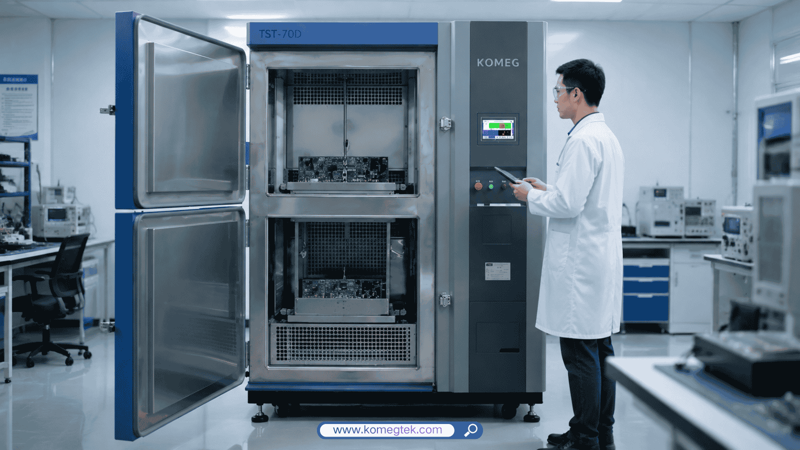
The IEC 60068-2-14 standard (Environmental Testing – Test N: Change of Temperature) defines standardized test procedures for evaluating the ability of electronic components, assemblies, and industrial products to withstand rapid temperature variations.
In real-world applications, products frequently experience sudden thermal shifts caused by harsh environmental conditions, rapid transportation, outdoor operation, or equipment power-ups in extreme climates.
Rapid temperature transitions induce severe mechanical stress because adjacent materials expand and contract at different rates due to mismatched Coefficients of Thermal Expansion (CTE).
For example, a semiconductor package contains silicon dies, solder joints, epoxy compounds, and metal lead frames. Repeated thermal swings generate significant internal strain, accelerating structural degradation before field deployment.
Thermal shock testing according to IEC 60068-2-14 accelerates these stress conditions in a controlled laboratory environment to identify potential reliability issues during the R&D stage.
Common Failure Mechanisms Detected
Solder Joint Cracking
Cyclic mechanical stress can create micro-cracks inside PCB solder joints, resulting in intermittent electrical failures and reduced assembly durability.
Packaging Delamination
Mismatch in CTE values can cause separation between silicon dies, epoxy molding compounds, substrates, and internal bonding layers.
Hermetic Seal Degradation
Thermal strain can compromise glass-to-metal seals, sensor housing gaskets, and protective enclosures, allowing moisture or contaminant ingress.
Electrical Parameter Drift
Mechanical strain may cause temporary or permanent changes in resistance, capacitance, signal timing, and operational stability.
2. Comprehensive Analysis of IEC 60068-2-14 Test Methods
IEC 60068-2-14 provides four different test methods depending on the required temperature change speed, transfer mechanism, and heat transfer medium.
The main test methods include:
Test Na: Rapid Change of Temperature with Prescribed Transfer Time (Air-to-Air)
Test Nb: Change of Temperature with Specified Rate of Change (Single Chamber)
Test Nc: Rapid Change of Temperature Using Two Fluid Baths (Liquid-to-Liquid)
Test Nd: Rapid Change of Temperature Using One Fluid Bath (Single Liquid Tank)
Test Na: Rapid Change of Temperature with Prescribed Transfer Time
Testing Methodology
Test Na is one of the most widely adopted air-to-air thermal shock testing methods.
During testing, the specimen is rapidly transferred between two separate chambers maintained at extremely high and low temperatures using an automated transfer mechanism.
This rapid transition exposes the specimen to sudden thermal gradients and creates severe thermal stress conditions.
Transfer Time Requirement
The physical transfer between hot and cold zones must be completed within the specified time requirement.
For standard applications:
Transfer time: ≤ 10 seconds
Fast transfer minimizes exposure to ambient conditions and ensures the specimen experiences true thermal shock conditions.
Dwell Time and Applications
After entering each temperature zone, the specimen remains static until it reaches thermal equilibrium.
The dwell time is typically 10–30 minutes, depending on specimen thermal mass and test requirements.
Common applications include:
Automotive electronic control units (ECUs)
Aerospace sensors
LED lighting modules
Semiconductor packages
EV battery management electronics
Test Nb: Change of Temperature with Specified Rate of Change
Testing Methodology
Unlike Test Na, Test Nb keeps the specimen stationary inside a single environmental test chamber.
The chamber temperature increases and decreases at a controlled linear rate to simulate gradual environmental temperature changes.
Ramp Rates and Applications
Common temperature change rates include:
1°C/min
5°C/min
10°C/min
15°C/min
Typical applications include:
System-level electronic enclosures
Industrial control cabinets
Heavy power equipment
Complete battery packs
This method is suitable when physical sample movement is impractical.
Test Nc and Test Nd: Liquid Bath Thermal Shock Methods
Test Nc: Two Fluid Baths
Test Nc transfers specimens between two inert liquid tanks maintained at different extreme temperatures.
The transfer process is completed within the required time limit.
Because liquid provides higher heat transfer efficiency than air, this method can generate extremely rapid temperature transitions.
Typical applications include:
Military components
Semiconductor packages
High-reliability electronic devices
Test Nd: Single Fluid Bath
Test Nd immerses the specimen in a single liquid bath where the temperature is rapidly changed between hot and cold conditions.
This method is mainly used for:
Specialized material evaluation
Thermal endurance research
Component-level stress testing
3. Engineering Requirements for Test Na Compliance
To achieve reliable IEC 60068-2-14 Test Na performance, a thermal shock test chamber must satisfy strict mechanical and thermal requirements.
A. High-Speed Transfer Mechanism
Compliance Requirement
The specimen transfer between hot and cold zones must be completed within:≤ 10 seconds
Engineering Solution
High-performance thermal shock chambers use:
Pneumatic or motor-driven transfer systems
Precision positioning sensors
Vibration reduction structures
Stable mechanical movement systems
These designs ensure rapid transfer while protecting sensitive electronic components from unnecessary mechanical impact.
B. Fast Temperature Recovery Performance
Compliance Requirement
After specimen transfer, the chamber temperature must quickly return to the required test condition within the specified tolerance range.
Engineering Solution
Fast temperature recovery requires:
High-capacity refrigeration systems
Efficient heating systems
Optimized airflow design
Thermal management structures
A chamber with insufficient recovery capability may experience:
Longer test cycles
Temperature instability
Reduced test accuracy
C. Temperature Uniformity and Airflow Management
Temperature uniformity ensures that all specimens experience consistent thermal stress.
Key design factors include:
High-performance circulation fans
Optimized air duct design
Proper sensor placement
Uniform airflow distribution
A well-designed airflow system improves test repeatability and measurement accuracy.
4. Thermal Load Considerations During Thermal Shock Testing
When selecting a thermal shock chamber, engineers must evaluate different thermal loads to prevent temperature recovery delays and test cycle distortion.
The total thermal requirement mainly consists of:
Thermal load generated by the specimen itself
Heat generated by powered electronic samples
1. Specimen Thermal Mass Load
When a heavy specimen enters a temperature zone, it absorbs or releases significant thermal energy.
Large metal assemblies usually require much higher heating or cooling capacity compared with lightweight electronic boards.
Insufficient chamber capacity may result in:
Slow temperature recovery
Extended test duration
Unstable test conditions
Therefore, specimen weight, material properties, and size must be considered during chamber selection.
2. Active Heat Load from Powered Samples
Modern electronic products are often tested while operating.
Examples include:
ECU modules
Battery control boards
Power converters
The heat generated during operation directly affects chamber thermal balance.
For active testing, engineers should consider:
Additional refrigeration capacity
Proper cable access sealing
Optimized airflow management
Proper cable port sealing also helps prevent:
Cold air leakage
Frost formation
Temperature instability
during low-temperature testing.
3. Engineering Sizing Checklist for Chamber Selection
Before selecting an Air-to-Air Thermal Shock Chamber, confirm the following parameters:
UUT Dimensions and Mass
Consider the total size and weight of test samples, including fixtures and baskets.
Operating Power
Evaluate the maximum continuous heat generated by powered samples.
Temperature Range
Common configurations include:
-40°C to +150°C
-55°C to +150°C
-65°C to +150°C
Test Method Requirement
Confirm whether the application requires:
Physical transfer between hot and cold zones (Test Na)
Controlled temperature ramp rate (Test Nb)
5. Frequently Asked Questions (FAQ)
Q1: What is the main difference between IEC 60068-2-14 Test Na and Test Nb?
A: Test Na uses rapid physical movement of the specimen between separate hot and cold zones within the required transfer time to generate strong thermal stress.
Test Nb changes temperature at a controlled rate inside a single chamber without physically moving the specimen.
Q2: What is the structural difference between a 2-zone and a 3-zone thermal shock chamber?
A: A 2-zone thermal shock chamber physically moves the sample between hot and cold zones using a transfer mechanism.
A 3-zone thermal shock chamber keeps the specimen stationary in a middle test zone while hot and cold airflow alternates.
Three-zone systems reduce mechanical movement and are suitable for sensitive or heavy specimens.
Q3: What temperature tolerance is required for IEC 60068-2-14 testing?
A: Temperature tolerance depends on the selected test method and test conditions.
A qualified thermal shock chamber should provide:
Accurate temperature control
Stable recovery performance
Reliable temperature uniformity
to ensure repeatable test results.
IEC 60068-2-14 thermal shock testing is an essential reliability evaluation method for automotive, semiconductor, aerospace, and industrial electronic products.
By accelerating thermal stress under controlled laboratory conditions, manufacturers can identify potential mechanical and electrical weaknesses before products enter the market.
Achieving reliable test results requires careful consideration of:
Test method selection
Transfer speed
Temperature recovery capability
Airflow management
Thermal load characteristics
Chamber configuration
A properly designed thermal shock testing system helps manufacturers improve product reliability, reduce field failures, and meet demanding environmental testing requirements.