
A Walk-In Environmental Test Chamber is a large-scale, enclosed test facility designed to simulate and precisely control a wide range of environmental conditions for the purpose of evaluating the performance, reliability, durability, and stability of large-sized products, components, materials, or complete assemblies. Unlike small benchtop environmental chambers, walk-in models feature a room-sized interior (typically ranging from 8 m³ to over 100 m³, depending on application requirements) that allows operators to enter the chamber for specimen placement, monitoring, and maintenance.
Its core operational principle is based on a closed-loop automatic control system, which realizes continuous and stable environmental regulation through a cycle of sensing → signal processing → comparison → actuation → circulation → feedback correction → stabilization. This closed-loop mechanism ensures that the internal environmental parameters (primarily temperature and humidity, and occasionally pressure, corrosive gas, dust, or light) remain consistent with the preset values, even when external environmental conditions change, or the heat/humidity load of the test specimen fluctuates.
1. Core Structural Components and Their Functions
The stable operation of a Walk-In Environmental Test Chamber relies on the coordinated work of multiple structural systems, each with clear functional positioning and technical requirements. The main components are as follows:
1.1 Insulated Chamber Body
The chamber body is the foundation of environmental isolation, responsible for preventing heat and moisture exchange between the internal test environment and the external ambient environment, thereby reducing energy consumption and ensuring the stability of internal parameters. Its structural design and material selection are critical to insulation performance:
- Structure: Adopts a double-layer or multi-layer airtight structure, with the inner wall, outer wall, and intermediate insulation layer forming an integrated sealed system. The inner wall is usually made of SUS304 or SUS316L stainless steel, which has corrosion resistance, high-temperature resistance, and easy cleaning properties; the outer wall is generally made of cold-rolled steel plate with electrostatic spraying treatment to enhance corrosion resistance and appearance integrity. The joint between the wall panels, as well as the connection between the chamber body and the door, is equipped with high-temperature and low-temperature resistant silicone rubber sealing strips, which are compressed to form an airtight seal, effectively preventing air leakage.
- Insulation Layer: Filled with high-density polyurethane foam (density ≥ 40 kg/m³) or rock wool, with a thickness of 100 mm to 200 mm, depending on the temperature range of the chamber. Polyurethane foam is widely used due to its excellent thermal insulation performance, low thermal conductivity (≤ 0.024 W/(m·K)), and good moisture-proof performance; rock wool is more suitable for chambers with higher temperature ranges (above 150°C) due to its better high-temperature resistance.
- Accessories: Equipped with observation windows (made of double-layer tempered hollow glass with anti-condensation heating function) to facilitate real-time observation of the test specimen without opening the door; equipped with adjustable test platforms (made of stainless steel mesh or solid plates) to meet the placement needs of different sizes and weights of specimens; equipped with drainage holes and pipelines at the bottom to discharge condensed water generated during the dehumidification process.
1.2 Air Handling Unit (AHU)
The air handling unit is the core component responsible for adjusting the temperature and humidity of the air in the chamber, usually installed on the top or side of the chamber body, and connected to the internal space of the chamber through air supply and return air ducts. Its internal structure includes:
- Heating System: Composed of electric heating elements, heating tubes, and temperature protection devices. The heating elements are usually nickel-chromium alloy (Ni-Cr) heating wires or heating tubes, which have high heating efficiency, stable performance, and long service life. The heating power is adjustable, ranging from several kilowatts to hundreds of kilowatts, depending on the volume of the chamber and the required heating rate. To prevent local overheating, the heating elements are evenly arranged in the air duct, and a temperature sensor is installed near the heating area to trigger overheat protection when the temperature exceeds the safe range.
- Cooling System: Composed of a refrigeration compressor, condenser, expansion valve, evaporator, and refrigerant pipeline. The refrigeration system is divided into single-stage refrigeration and cascade (two-stage) refrigeration, depending on the minimum temperature required by the chamber.
- Humidification and Dehumidification System: Includes humidifiers, dehumidifiers, water supply pipelines, and drainage pipelines, responsible for adjusting the relative humidity (RH) in the chamber.
- Circulation Fan: Usually a centrifugal fan with high air volume and low noise, equipped with a frequency converter to adjust the air volume. The fan is responsible for forcing the air in the chamber to circulate through the air handling unit, so that the heated, cooled, humidified, or dehumidified air is evenly distributed to every corner of the chamber.
- Air Filter: Installed at the air return port of the air handling unit, usually a G4 primary filter and an F5 medium-efficiency filter, which can filter out dust and impurities in the air, prevent the blockage of heating/cooling coils and sensors, and ensure the cleanliness of the test environment.
1.3 Control System
The control system is the “brain” of the Walk-In Environmental Test Chamber, responsible for collecting, processing, and analyzing environmental parameter signals, and controlling the operation of each functional system to achieve precise regulation of the test environment. Its main components include:
- Controller: Adopts a programmable logic controller (PLC) as the core, matched with a touchscreen human-machine interface (HMI). The PLC has strong anti-interference ability, high control precision, and can realize complex logic control and program operation; the touchscreen HMI is used for parameter setting, real-time data display, program editing, and alarm prompt, with a user-friendly operation interface.
- Control Algorithm: Uses the proportional-integral-derivative (PID) control algorithm, and some high-precision chambers also integrate fuzzy logic control to improve the response speed and stability of the system. The PID algorithm adjusts the output of the heating, cooling, humidification, and dehumidification systems according to the deviation between the actual measured value and the preset value, thereby reducing the fluctuation of parameters and ensuring that the environmental conditions are stable within the allowable error range.
- Data Logging and Storage: Equipped with a data logging module, which can record the real-time temperature, humidity, and other parameters during the test process at set time intervals (usually 1s to 60s). The data can be stored in the internal memory of the controller (storage capacity ≥ 100,000 groups) or exported to a computer through a USB interface or LAN for data analysis and report generation.
- Remote Control Function: Some advanced models support remote monitoring and control through LAN, Wi-Fi, or IoT technology. Operators can view real-time test data, adjust parameters, and start/stop the test through a computer or mobile terminal, which is convenient for remote management and monitoring.
1.4 Sensor System
The sensor system is responsible for collecting real-time environmental parameters in the chamber and converting them into electrical signals to transmit to the control system. The accuracy and stability of the sensors directly affect the control precision of the chamber:
- Temperature Sensor: Usually uses a high-precision PT100 platinum resistance sensor, which has a measurement range of -200°C to +850°C, an accuracy of ±0.1°C to ±0.3°C, and good stability and repeatability. The sensor is installed in the air return duct of the chamber to measure the average temperature of the circulating air, and some chambers are also equipped with additional sensors near the test specimen to monitor the temperature of the specimen surface.
- Humidity Sensor: Adopts a capacitive relative humidity sensor, which has a measurement range of 0–100% RH, an accuracy of ±1.0% RH to ±2.0% RH, and strong anti-interference ability. The sensor is usually installed together with the temperature sensor to ensure that the measured humidity value is consistent with the temperature environment of the circulating air.
- Other Sensors: For chambers with special test requirements (such as pressure test, corrosion test), additional sensors are installed, such as pressure sensors (measurement range 0–1.0 MPa, accuracy ±0.5% FS) and corrosive gas concentration sensors, to monitor the corresponding environmental parameters.
1.5 Safety and Protection System
To ensure the safety of operators, test specimens, and the chamber itself, the Walk-In Environmental Test Chamber is equipped with a complete safety protection system, including:
- Over-temperature Protection: When the temperature in the chamber exceeds the preset safe value (usually 5–10°C higher than the maximum test temperature), the heating system will be automatically cut off, and an alarm will be triggered to prevent the specimen from being damaged or the chamber from being overheated.
- Over-pressure Protection: For chambers with pressure control functions, a pressure relief valve and a pressure sensor are installed. When the internal pressure exceeds the safe range, the pressure relief valve will automatically open to release pressure, and the control system will stop the pressure supply and trigger an alarm.
- Compressor Protection: The refrigeration compressor is equipped with overload protection, overcurrent protection, and low-voltage protection. When the compressor is overloaded, the current is too large, or the refrigerant pressure is too low, the compressor will be automatically shut down to avoid damage to the compressor.
- Door Interlock Protection: When the chamber door is not closed tightly, the heating, cooling, and humidification systems will not start, and the fan will stop running (or run at a low speed) to prevent the operator from being scalded, frozen, or exposed to harmful environments. Some models also have a door-opening alarm function.
- Water Level Protection: For steam humidifiers, a water level sensor is installed in the water tank. When the water level is too low, the humidifier will stop working, and an alarm will be triggered to prevent the humidifier from being burned due to dry heating.
- Power Failure Protection: Equipped with a power failure memory function. When the power is suddenly cut off, the controller will save the current test parameters and program progress. After the power is restored, the test can continue from the point of interruption, avoiding test failure due to power failure.
2. Temperature Control Principle
Temperature control is one of the core functions of a Walk-In Environmental Test Chamber, which realizes the adjustment of the internal temperature within the set range (usually -70°C to +150°C, or even wider) through the coordinated work of the heating system and the cooling system, and maintains the temperature stability and uniformity through the PID closed-loop control.
2.1 Heating System Working Principle
The heating system adopts an electric heating mode, which has the advantages of fast heating speed, stable heating, and easy adjustment. Its specific working process is as follows:
- Signal Trigger: When the temperature sensor detects that the actual temperature in the chamber is lower than the preset temperature, the control system (PLC) will receive the temperature deviation signal and output a control signal to the heating system.
- Heating Operation: The heating system receives the control signal, and the electric heating elements (nickel-chromium heating wires/tubes) are energized to generate heat. The heating power is adjusted by the PID algorithm according to the temperature deviation: the larger the deviation, the higher the heating power; the smaller the deviation, the lower the heating power (or intermittent heating).
- Air Heating and Circulation: The circulation fan forces the air in the chamber to flow through the heating area, and the air absorbs the heat generated by the heating elements, resulting in an increase in temperature. The heated air is then sent back to the chamber through the air supply duct, forming a closed-loop air circulation.
- Temperature Stabilization: As the air temperature in the chamber gradually rises, the temperature deviation between the actual value and the preset value decreases. The PID algorithm continuously adjusts the heating power, and when the actual temperature reaches the preset value, the heating system maintains a small power output (or intermittent output) to offset the heat loss of the chamber body, ensuring that the temperature remains stable within the allowable error range (usually ±0.5°C).
The heating range of the system is usually +70°C to +150°C, and some high-temperature walk-in chambers can reach +200°C or higher by increasing the heating power and optimizing the insulation structure. The heating rate is adjustable, generally 1–3°C/min, and can reach 5°C/min or higher for special requirements.
2.2 Cooling System Working Principle
The cooling system is responsible for reducing the temperature in the chamber to the preset low temperature, and its working principle is based on the vapor-compression refrigeration cycle. According to the minimum temperature required by the chamber, it is divided into single-stage refrigeration and cascade (two-stage) refrigeration.
2.2.1 Single-Stage Refrigeration Cycle (for Minimum Temperature ≥ -40°C)
Single-stage refrigeration is the most common cooling mode, which consists of four core components: compressor, condenser, expansion valve, and evaporator, connected by refrigerant pipelines to form a closed refrigeration loop. The specific working process is as follows:
- Compression Stage: The refrigeration compressor (usually a scroll compressor or a piston compressor) sucks in low-pressure, low-temperature refrigerant vapor (such as R404A, R508B, or R134a) from the evaporator, and compresses it into high-pressure, high-temperature refrigerant gas (pressure: 1.5–2.5 MPa; temperature: 70–90°C).
- Condensation Stage: The high-pressure, high-temperature refrigerant gas is sent to the condenser (air-cooled or water-cooled). In the condenser, the refrigerant gas exchanges heat with the external cooling medium (air or water), releases a large amount of heat, and condenses into high-pressure, low-temperature refrigerant liquid (temperature: 30–40°C).
- Throttling Stage: The high-pressure, low-temperature refrigerant liquid passes through the expansion valve (or capillary tube), which acts as a throttling and decompression device. The refrigerant liquid is suddenly decompressed, and its pressure and temperature drop sharply, forming a low-pressure, low-temperature mixture of liquid and vapor (temperature: -20°C to -40°C).
- Evaporation Stage: The low-pressure, low-temperature refrigerant mixture enters the evaporator (installed in the air handling unit). The air in the chamber (forced by the circulation fan) flows through the outer surface of the evaporator, and the heat in the air is absorbed by the refrigerant, resulting in a decrease in the air temperature. The refrigerant absorbs heat and evaporates into low-pressure, low-temperature vapor, which is then sucked into the compressor to start the next cycle.
2.2.2 Cascade (Two-Stage) Refrigeration Cycle (for Minimum Temperature ≤ -40°C)
When the minimum temperature required by the chamber is lower than -40°C (such as -70°C, -100°C), the single-stage refrigeration cycle cannot meet the requirements (because the evaporation temperature of the refrigerant is limited, and the compression ratio of the compressor cannot be too large, otherwise the compressor will be overloaded and damaged). At this time, a cascade refrigeration cycle is adopted, which consists of two independent single-stage refrigeration systems: the high-temperature stage (HT stage) and the low-temperature stage (LT stage).
- High-Temperature Stage (HT Stage): Uses a common refrigerant (such as R404A) and is responsible for cooling the condenser of the low-temperature stage. Its working principle is the same as that of the single-stage refrigeration cycle. The evaporator of the high-temperature stage is closely connected to the condenser of the low-temperature stage, and the heat released by the low-temperature stage refrigerant during condensation is absorbed by the high-temperature stage refrigerant.
- Low-Temperature Stage (LT Stage): Uses a low-temperature refrigerant (such as R23, R14, or R508B) with a low boiling point and is responsible for directly cooling the air in the chamber. Its evaporator is installed in the air handling unit of the chamber, and the working principle is the same as that of the single-stage refrigeration cycle. Since the condenser of the low-temperature stage is cooled by the high-temperature stage, the evaporation temperature of the low-temperature stage refrigerant can be reduced to -70°C or lower, thereby realizing the low-temperature control of the chamber.
The cascade refrigeration cycle has the advantages of high cooling efficiency, stable operation, and wide low-temperature range, but its structure is more complex, and the cost and energy consumption are higher than those of the single-stage refrigeration cycle.
2.3 Temperature Control Logic and Uniformity Guarantee
The temperature control of the Walk-In Environmental Test Chamber adopts a closed-loop PID control logic, which ensures the precision and stability of the temperature:
- Closed-Loop Control: The temperature sensor continuously collects the actual temperature in the chamber and transmits it to the PLC. The PLC compares the actual temperature with the preset temperature to calculate the temperature deviation, and then adjusts the output of the heating and cooling systems according to the PID algorithm. The adjusted air is circulated back to the chamber, and the sensor collects the new temperature again, forming a continuous closed-loop feedback and correction process.
- PID Parameter Adjustment: The PID algorithm has three parameters: proportional coefficient (P), integral coefficient (I), and derivative coefficient (D). The proportional coefficient (P) determines the response speed of the system to the temperature deviation; the integral coefficient (I) eliminates the static error of the system, ensuring that the actual temperature can stably reach the preset value; the derivative coefficient (D) predicts the change trend of the temperature deviation, reducing the overshoot of the system and improving the stability of the system. The PID parameters can be automatically adjusted by the controller according to the test conditions, or manually adjusted by the operator according to experience.
- Temperature Uniformity: The temperature uniformity of the Walk-In Environmental Test Chamber is an important performance index, which refers to the maximum temperature difference between different positions in the chamber. To ensure uniformity (usually ±0.5°C to ±1.0°C), the following measures are adopted: ① Forced air circulation: The centrifugal fan with frequency conversion adjusts the air volume to ensure that the air flows uniformly in the chamber; ② Reasonable air distribution: Adopt the “top supply, bottom return” or “side supply, side return” air distribution mode, and install baffles and diffusers at the air supply port to make the air evenly distributed to every corner of the chamber; ③ Even arrangement of heating and cooling elements: The heating and cooling elements are evenly arranged in the air duct to avoid local overheating or overcooling; ④ Optimization of the chamber structure: The internal structure of the chamber is designed to be smooth, reducing air resistance and avoiding the formation of dead corners.
3. Humidity Control Principle
Humidity control is another core function of the Walk-In Environmental Test Chamber, which adjusts the relative humidity (RH) in the chamber within the set range (usually 20–98% RH) through the humidification system and dehumidification system, and coordinates with the temperature control system to ensure the stability of the humidity. The humidity control is based on the principle of air-water vapor balance, and the control precision is usually ±1.5–3.0% RH.
3.1 Humidification System Working Principle
The humidification system is responsible for increasing the relative humidity in the chamber, and there are two common humidification methods: steam (boiler) humidification and ultrasonic/water pan humidification. The selection of the humidification method depends on the required humidity range, test precision, and energy consumption requirements.
3.1.1 Steam (Boiler) Humidification
Steam humidification is a high-precision, high-efficiency humidification method, which is widely used in Walk-In Environmental Test Chambers that require high humidity (60–98% RH) and high precision. Its working principle is as follows:
- Water Supply and Heating: The humidification system is equipped with a stainless steel water tank and an electric heating boiler. The water tank is connected to the tap water pipeline (or pure water pipeline) to ensure a continuous water supply. The electric heating boiler heats the water in the tank to boiling, generating pure steam (saturated steam).
- Steam Injection: The generated saturated steam is injected into the air duct of the air handling unit through a steam nozzle. The steam is fully mixed with the circulating air in the duct, and the water vapor in the steam is absorbed by the air, resulting in an increase in the relative humidity of the air.
- Humidity Regulation: The control system adjusts the heating power of the boiler according to the humidity deviation (the difference between the actual humidity and the preset humidity). The larger the deviation, the higher the heating power, the more steam generated, and the faster the humidity rises; when the actual humidity reaches the preset value, the boiler maintains a small power output to ensure the stability of the humidity.
Advantages of steam humidification: fast response speed, high humidification precision, clean steam (no impurities), and no pollution to the test specimen; disadvantages: high energy consumption, high requirements for water quality (need to use pure water to avoid scale formation in the boiler and nozzle).
3.1.2 Ultrasonic / Water Pan Humidification
Ultrasonic humidification and water pan humidification are low-energy, low-cost humidification methods, which are suitable for test scenarios that require moderate humidity (30–70% RH) and general precision.
- Ultrasonic Humidification: Uses an ultrasonic transducer to convert electrical energy into ultrasonic energy. The ultrasonic energy acts on the water surface in the humidifier, making the water atomized into tiny water droplets (diameter ≤ 5 μm). The circulating fan sends the atomized water droplets into the chamber, and the water droplets evaporate into water vapor in the air, thereby increasing the relative humidity. Its advantages are low energy consumption, quiet operation, and fast humidification speed; disadvantages are that the humidification precision is lower than that of steam humidification, and the atomized water droplets may condense on the surface of the test specimen if the air circulation is not smooth.
- Water Pan Humidification: A water pan is installed in the air handling unit, and the water in the pan is heated by an electric heating tube to evaporate into water vapor. The circulating air absorbs the water vapor and brings it into the chamber to increase the humidity. Its advantages are simple structure, low cost, and easy maintenance; disadvantages are slow humidification speed, low humidification precision, and easy generation of scale in the water pan.
3.2 Dehumidification System Working Principle
The dehumidification system is responsible for reducing the relative humidity in the chamber, and there are two common dehumidification methods: cooling (condensation) dehumidification and desiccant/molecular sieve dehumidification. The selection of the dehumidification method depends on the required minimum humidity and test conditions.
3.2.1 Cooling (Condensation) Dehumidification (Most Common)
Cooling dehumidification is based on the principle that the saturation water vapor capacity of air decreases with the decrease of temperature. When the air temperature is lower than its dew point temperature, the water vapor in the air will condense into liquid water, which is then discharged, thereby reducing the relative humidity of the air. Its working principle is as follows:
- Air Cooling: The circulation fan forces the air in the chamber to flow through the evaporator of the cooling system. The evaporator is cooled by the refrigerant, and the surface temperature of the evaporator is lower than the dew point temperature of the air.
- Moisture Condensation: When the air flows through the surface of the evaporator, the water vapor in the air condenses into liquid water (condensate) due to cooling, and the condensate flows into the water pan at the bottom of the evaporator and is discharged out of the chamber through the drainage pipeline.
- Dehumidified Air Circulation: The air after dehumidification (with reduced water vapor content) is heated or cooled to the preset temperature by the heating or cooling system, and then sent back to the chamber, forming a closed-loop dehumidification cycle.
Cooling dehumidification is suitable for the humidity range of 30–90% RH, with the advantages of simple structure, low energy consumption, and stable dehumidification effect; disadvantages are that it is difficult to achieve very low humidity (below 20% RH), and the dehumidification effect is affected by the temperature (the lower the temperature, the worse the dehumidification effect).
3.2.2 Desiccant / Molecular Sieve Dehumidification
Desiccant dehumidification is suitable for test scenarios that require very low humidity (below 20% RH) or low-temperature conditions (where cooling dehumidification is ineffective). Its working principle is based on the adsorption capacity of desiccant materials for water vapor, and the common desiccant materials include molecular sieve, silica gel, and activated alumina.
The desiccant dehumidification system usually adopts a rotating desiccant wheel structure, which is divided into two areas: the adsorption area and the regeneration area. The specific working process is as follows:
- Adsorption Dehumidification: The circulating air in the chamber flows through the adsorption area of the desiccant wheel. The water vapor in the air is adsorbed by the desiccant material on the wheel, and the dehumidified air is sent back to the chamber.
- Desiccant Regeneration: As the desiccant in the adsorption area gradually becomes saturated, the desiccant wheel rotates, and the saturated desiccant enters the regeneration area. In the regeneration area, hot air (heated by an electric heater) flows through the desiccant wheel, and the water vapor adsorbed by the desiccant is desorbed (evaporated) and discharged out of the chamber along with the hot air. The regenerated desiccant rotates back to the adsorption area to continue the dehumidification work.
Advantages of desiccant dehumidification: can achieve very low humidity (even below 10% RH), not affected by temperature, and stable dehumidification effect; disadvantages are high energy consumption (need to heat the regeneration air), complex structure, and high maintenance cost.
3.3 Humidity Control Logic and Coordination with Temperature Control
The humidity control of the Walk-In Environmental Test Chamber also adopts a closed-loop PID control logic, and its control process is similar to that of temperature control:
- Closed-Loop Control: The humidity sensor collects the actual relative humidity in the chamber and transmits it to the PLC. The PLC compares the actual humidity with the preset humidity to calculate the humidity deviation, and then activates the humidification system or dehumidification system according to the PID algorithm to adjust the humidity.
- Coordination with Temperature Control: Relative humidity (RH) is a relative parameter that is closely related to temperature. The same amount of water vapor in the air will have different relative humidity at different temperatures: the higher the temperature, the lower the relative humidity; the lower the temperature, the higher the relative humidity. Therefore, the control system needs to coordinate the temperature and humidity control: when adjusting the temperature, the humidity will change accordingly, and the control system will automatically adjust the humidification or dehumidification system to ensure that both temperature and humidity meet the preset requirements. For example, when the chamber is heated, the relative humidity will decrease, and the control system will activate the humidification system to supplement water vapor; when the chamber is cooled, the relative humidity will increase, and the control system will activate the dehumidification system to remove excess water vapor.
4. Air Circulation System and Uniformity Guarantee
The air circulation system is an important part of the Walk-In Environmental Test Chamber, which is responsible for realizing the uniform distribution of temperature and humidity in the chamber, eliminating hot and cold spots, and ensuring that the test specimen is in a stable and uniform environmental condition. Its working principle and key design points are as follows:
4.1 Core Components of the Air Circulation System
- Circulation Fan: Usually a centrifugal fan with high air volume, low noise, and high pressure. The fan is equipped with a frequency converter, which can adjust the air volume according to the test requirements (usually 5–15 m/s). The power of the fan ranges from several kilowatts to dozens of kilowatts, depending on the volume of the chamber and the required air circulation speed.
- Air Supply and Return Air Ducts: The air supply duct is installed on the top or side of the chamber, and the return air duct is installed on the bottom or opposite side of the air supply duct. The duct is made of stainless steel or galvanized steel plate, with a smooth inner surface to reduce air resistance. The air supply duct is equipped with diffusers and baffles to evenly distribute the air into the chamber; the return air duct is equipped with air filters to remove dust and impurities in the air.
- Air Distribution Plate: Installed at the air supply port and return air port, with evenly distributed holes, which can further optimize the air flow direction and ensure that the air flows uniformly in the chamber. The air distribution plate is usually made of stainless steel mesh or a perforated plate, which has good air permeability and corrosion resistance.
4.2 Air Circulation Mode and Working Process
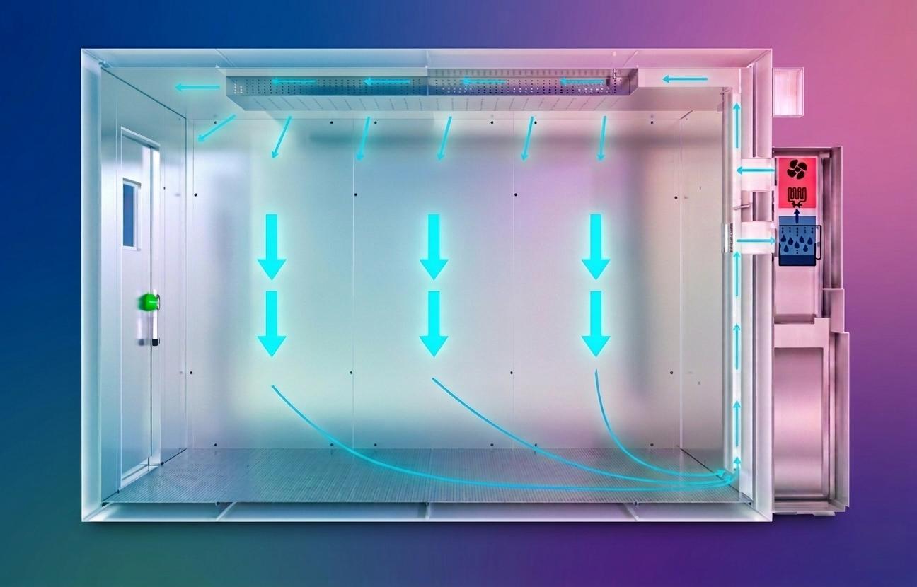
The most common air circulation mode of Walk-In Environmental Test Chambers is the “top supply, bottom return” vertical laminar flow mode, and some models adopt the “side supply, side return” horizontal flow mode, depending on the structure of the chamber and the test requirements. The working process of the air circulation system is as follows:
- Air Suction: The circulation fan sucks the air in the chamber into the air handling unit through the return air duct. The air first passes through the air filter to remove dust and impurities.
- Air Conditioning: The filtered air flows through the heating coil, cooling evaporator, humidifier, or dehumidifier in the air handling unit, and is adjusted to the preset temperature and humidity.
- Air Supply: The conditioned air is sent to the air supply duct by the circulation fan and is evenly distributed into the chamber through the diffusers and air distribution plates at the air supply port.
- Air Circulation: The air in the chamber flows from the air supply port to the return air port, forming a closed-loop circulation. During the circulation process, the air exchanges heat and moisture with the test specimen, and the temperature and humidity of the air change slightly. The changed air is sucked into the air handling unit again for adjustment, and the cycle repeats.
4.3 Measures to Ensure Air Uniformity
The air uniformity of the Walk-In Environmental Test Chamber directly affects the accuracy of the test results. To ensure that the temperature and humidity in the chamber are uniform, the following measures are usually taken in the design and operation of the air circulation system:
- Reasonable Fan Selection: Select a centrifugal fan with appropriate air volume and pressure to ensure that the air circulation speed in the chamber is sufficient (usually 0.5–2 m/s) and the air flow is stable.
- Optimized Duct Design: The air supply and return air ducts are designed according to the principle of equal resistance, ensuring that the air flow in each part of the duct is uniform and avoiding the phenomenon of uneven air supply caused by excessive local resistance.
- Uniform Air Distribution: Install diffusers and baffles at the air supply port to adjust the air flow direction and speed, making the air evenly distributed to every corner of the chamber. The air distribution plate at the return air port is designed to ensure that the air is sucked uniformly, avoiding local negative pressure or positive pressure.
- Elimination of Dead Corners: The internal structure of the chamber is designed to be smooth, avoiding the formation of air dead corners (such as sharp corners, narrow gaps). The test platform is installed at a certain height from the bottom of the chamber to ensure that the air can flow smoothly under the platform.
- Frequency Conversion Adjustment: The circulation fan is equipped with a frequency converter, which can adjust the air volume according to the test conditions. For example, when the chamber is in a low-temperature or high-humidity environment, the air volume can be appropriately increased to improve the uniformity of temperature and humidity.
5. Full Operational Cycle of the Walk-In Environmental Test Chamber (Simplified)
The operational process of the Walk-In Environmental Test Chamber is a continuous closed-loop cycle, which can be divided into the following steps:
- Test Preparation: The operator checks the chamber for air leakage, cleans the internal space and air filters, checks the water supply, power supply, and refrigerant status of each system, and places the test specimen on the test platform (ensuring that the specimen does not block the air supply and return air ports).
- Parameter Setting: The operator sets the test parameters through the touchscreen HMI, including the preset temperature, humidity, test duration, temperature/humidity ramp rate, and multi-step test profile (if needed). The controller stores the set parameters and starts the test program.
- Environmental Sensing: The temperature sensor and humidity sensor continuously collect the real-time temperature and humidity in the chamber, convert them into electrical signals, and transmit them to the PLC.
- Signal Processing and Comparison: The PLC receives the sensor signals, processes and analyzes them, and compares the actual measured values with the preset values to calculate the temperature and humidity deviations.
- System Actuation: According to the calculated deviations and the PID control algorithm, the PLC outputs control signals to activate the corresponding systems: if the actual temperature is lower than the preset value, the heating system is activated; if it is higher, the cooling system is activated; if the actual humidity is lower than the preset value, the humidification system is activated; if it is higher, the dehumidification system is activated.
- Air Circulation and Conditioning: The circulation fan forces the air in the chamber to circulate through the air handling unit, and the air is heated, cooled, humidified, or dehumidified to the preset temperature and humidity, then sent back to the chamber to form a closed-loop circulation.
- Parameter Stabilization: The PID algorithm continuously adjusts the output of each system according to the feedback signals of the sensors, reducing the temperature and humidity deviations, and ensuring that the internal environmental parameters of the chamber remain stable within the allowable error range.
- Test Execution: The test specimen is exposed to the stable controlled environment for the set test duration. During the test process, the controller records the real-time test data and monitors the operation status of each system. If an abnormal situation occurs (such as over-temperature, over-pressure), the alarm system is triggered, and the corresponding system is shut down to ensure the safety of the specimen and the chamber.
- Test Termination: When the test duration is reached, the controller automatically stops the operation of each system, and the operator opens the chamber door (after the internal temperature and humidity return to the ambient level, if necessary) to take out the test specimen and conduct performance testing and analysis on the specimen. The test data is exported and sorted to form a test report.
6. Typical Performance Specifications
The performance specifications of Walk-In Environmental Test Chambers vary according to the design and application requirements, and the typical specifications are as follows (for reference only):
- Temperature Range: -70°C to +150°C (common); -100°C to +200°C (high and low temperature models).
- Humidity Range: 20–98% RH (common); 10–98% RH (low humidity models).
- Temperature Uniformity: ±0.5°C to ±1.0°C (at normal temperature and humidity); ±1.0°C to ±2.0°C (at extreme temperatures).
- Humidity Uniformity: ±1.5–3.0% RH.
- Temperature Ramp Rate: Heating: 1–3°C/min (common); 5°C/min (high-speed models); Cooling: 0.5–2°C/min (common); 3°C/min (high-speed models).
- Chamber Volume: 10 m³ to 100 m³ (common); more than 100 m³ (customized models).
- Control Precision: Temperature: ±0.1°C to ±0.3°C; Humidity: ±1.0% RH to ±2.0% RH.
- Power Supply: 380V/50Hz (three-phase four-wire); Power: 10kW to 100kW (depending on volume and temperature range).
7. Summary
A Walk-In Environmental Test Chamber is a high-precision environmental control equipment based on the closed-loop PID control principle, which realizes the precise simulation and control of temperature and humidity (and other environmental parameters) through the coordinated work of multiple systems. Its core working principle can be summarized as follows:
- The heating system (electric heating elements) and cooling system (vapor-compression refrigeration cycle) work together to adjust the internal temperature of the chamber, with the cascade refrigeration cycle enabling low-temperature control below -40°C.
- The humidification system (steam or ultrasonic/water pan humidification) and dehumidification system (cooling condensation or desiccant adsorption) adjust the internal humidity of the chamber, and coordinate with the temperature control system to ensure the stability of both parameters.
- The air circulation system (centrifugal fan, air ducts, and air distribution components) realizes the uniform distribution of temperature and humidity in the chamber, eliminating hot and cold spots and ensuring the uniformity of the test environment.
- The control system (PLC + PID algorithm) collects and processes sensor signals, adjusts the output of each functional system in real time, and ensures that the environmental parameters remain stable within the preset range.
The Walk-In Environmental Test Chamber is widely used in aerospace, automotive, electronics, machinery, materials, and other fields. It can reliably reproduce extreme or steady environmental conditions (such as high temperature, low temperature, high humidity, and low humidity) to evaluate the performance, reliability, and durability of products under real-world or extreme working conditions, providing important technical support for product research and development, quality inspection, and production verification.