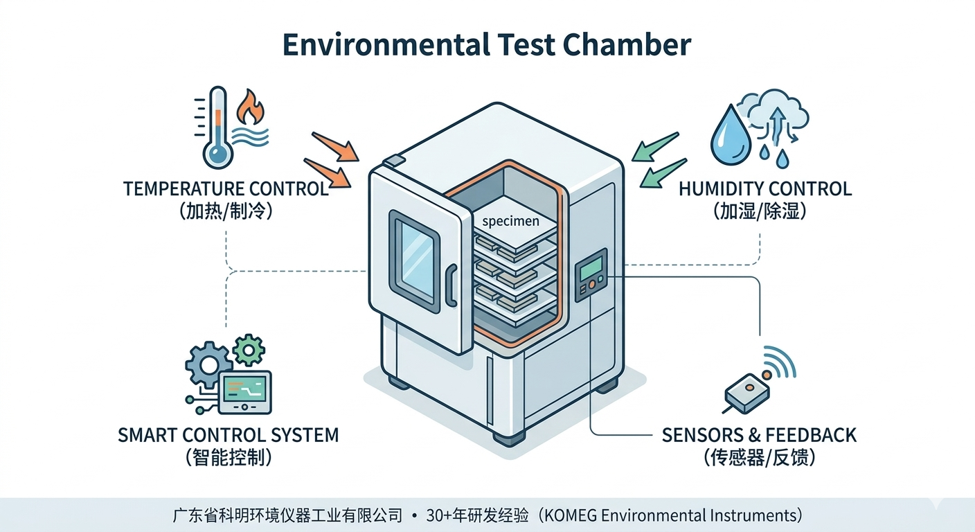
High-low temperature test chambers are primarily used for the reliability verification of industrial products. By simulating extreme thermal environments—including high-temperature soak, low-temperature soak, and thermal cycling—these chambers evaluate the performance indicators of components and materials across sectors such as electronics, automotive, aerospace, marine weaponry, and scientific research.
II. The Core Question: Why Can’t the Chamber Be “Fully Loaded”?
During technical consultations, engineers often ask: “What is the size of your test sample?” This is not merely to confirm physical fit but to ensure the authenticity of the simulated environment. According to industry standards, the effective volume of the chamber should be at least 3 to 5 times the total volume of the test samples.
Strictly avoiding a “fully loaded” chamber is based on the following three scientific principles:
01. Consistency of Airflow and Heat Exchange
Physical Mechanism: When samples are placed in the chamber, the cross-section of the air duct narrows, causing a localized increase in airflow velocity.
Standard Constraints: Relevant standards mandate that the airflow velocity around the test sample should not exceed 1.7 m/s. Under no-load conditions, the average velocity is typically between 0.6 and 0.8 m/s.
Impact: If samples occupy too much space, the flow velocity may surge by 50% to 100%. This leads to unnaturally fast heat exchange on the sample surface, resulting in “pseudo-test results” that do not reflect real-world conditions.
02. Protection of Environmental Parameter Uniformity
Physical Mechanism: Accuracy indicators (such as temperature uniformity) are measured under no-load conditions.
Impact: Larger samples create greater resistance to air circulation. Experimental data shows that the temperature difference between the windward and leeward sides can expand to 3°C–8°C, and in extreme cases, exceed 10°C, rendering the test data invalid.
03. Wall Radiation and Boundary Layer Effects
Physical Mechanism: Due to heat conduction, the airflow temperature near the chamber walls typically deviates from the center by 2°C–3°C, reaching up to 5°C at extreme high or low limits.
Recommendation: To avoid the “boundary layer temperature gradient” caused by the external environment, the space within 100mm–150mm of the chamber walls is considered non-utilizable.
III. Standardization: The “Correct Posture” for Sample Placement
To obtain precise test data, please adhere to the following placement guidelines:
1. Spatial Occupancy Requirements
Total Volume Ratio: The total volume of the products should not exceed 20% to 35% of the effective working space.
Heat-Generating Samples: If the sample generates heat during testing, the ratio should be kept below 10%.
Windward Cross-Sectional Area: The total area of the products perpendicular to the airflow should not exceed 35% to 50% of the chamber’s total cross-sectional area.
2. Spatial Positioning Rules
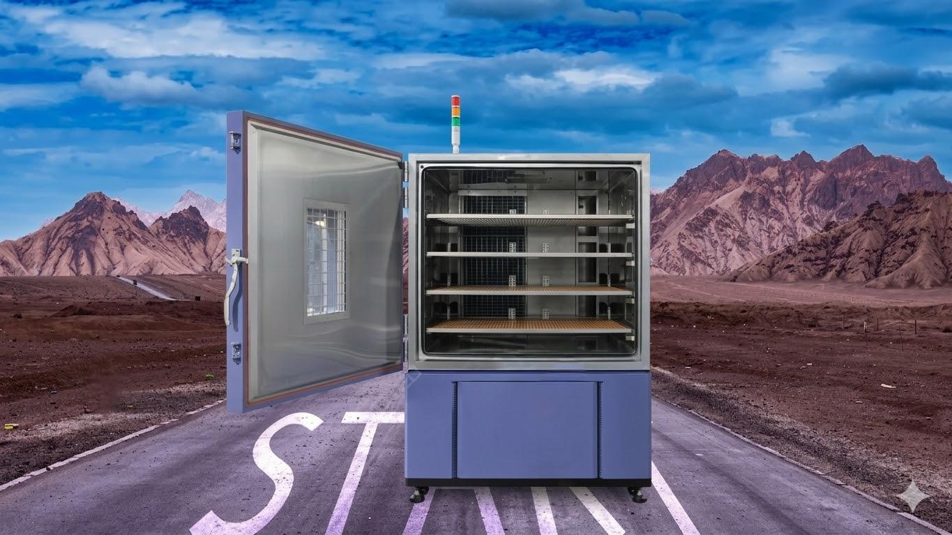
Centering Principle: Products should be placed in the geometric center of the workspace and must never be placed directly on the bottom surface of the chamber.
Spacing Principle: Maintain sufficient gaps between samples (at least 2cm recommended); keep a distance of at least 100mm–150mm from all walls.
Air Duct Clearance: Do not block the upper air supply vents or the lower return air vents.
3. External Wiring Specifications
Power or signal lines must be routed through the designated test hole. Cables should be neatly arranged and secured near the hole; never allow wires to tangle or knot inside the chamber. Ensure cable insulation is intact to prevent short circuits.
IV. Handling Special Samples (Expert Tips)
Liquids/Viscous Substances: Must be stored in sealed, temperature-resistant containers to prevent leakage and corrosion of the chamber interior.
Rubber Products: Place on a tray to prevent the rubber from adhering to the metal shelves at high temperatures.
Hazardous Materials: Strictly prohibit placing flammable, explosive, or self-igniting substances in standard chambers. For specialized explosion-proof models, strictly control temperature settings and prevent any liquid spillage.
Micro-components: Use mesh trays to allow airflow penetration.
When dealing with a large volume of samples, do not stack them to save time. Batch testing, although time-consuming, ensures the accuracy and authenticity of every data point. Scientific placement and reasonable loading are the strongest guarantees for successful product R&D and quality improvement.